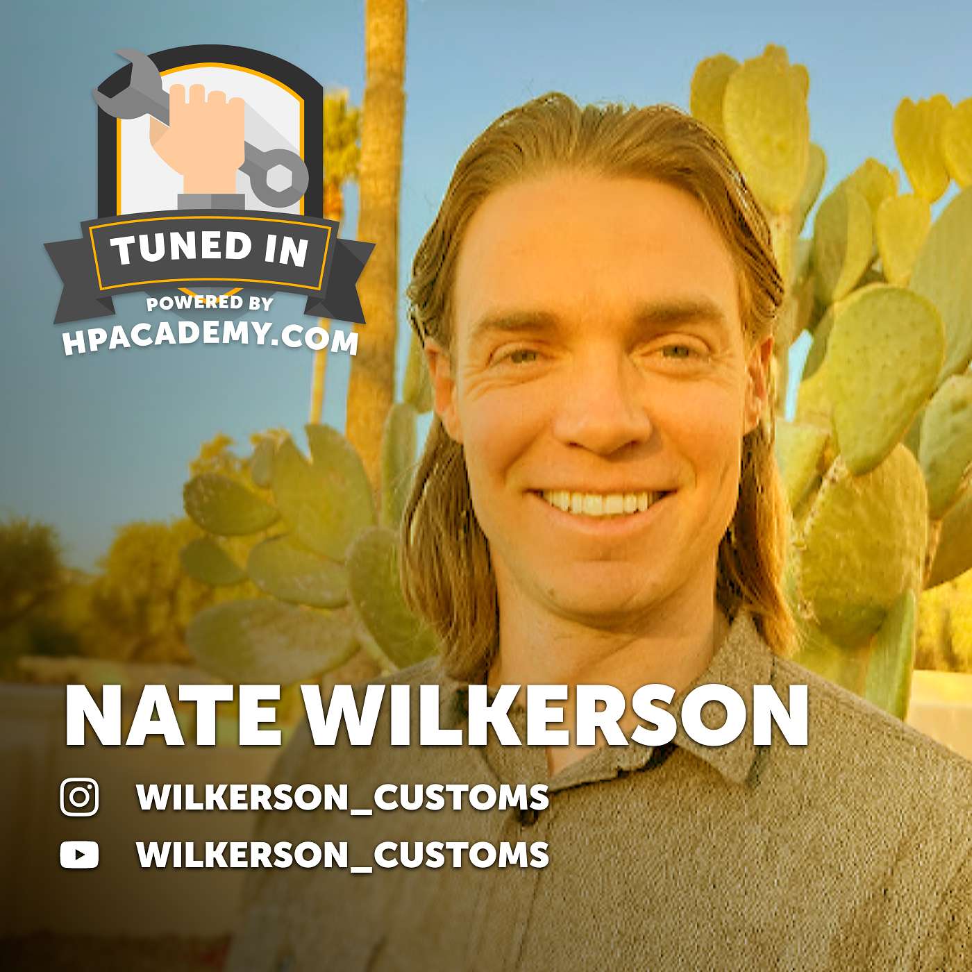
164: CAD: The Gateway to Making Dreams a Reality
About this episode
CAD is treated like the bridge between imagination and fabrication, with Nate Wilkerson’s SOLIDWORKS workflow used to validate suspension geometry, fitment, and clearance before anything gets built. The conversation connects off-road design history (Baja bugs and modern buggy layouts) to practical CAD-to-CNC realities: machining constraints, tolerances, and why FEA needs hand-checked validation. Generative design and 3D printing come up through turbo manifold examples, plus how CAD skills transfer across Fusion, SOLIDWORKS, and Blender.
We all dream up incredible vehicle concepts—Nate Wilkerson of Wilkerson Customs brings them to life. Combining engineering expertise, CAD design, and a lifelong passion for off-road racing, Nate has built a huge following by creating some of the most ambitious virtual vehicle concepts on the internet.
👉 Use the code ‘PODCAST500’ to get $500 OFF HPA's VIP Package: https://hpcdmy.co/podvip
In this episode of Tuned In, we dive into Nate’s background, from growing up in a machine shop and studying optical engineering to designing advanced laser systems for autonomous vehicles and military applications. Along the way, he developed a passion for mechanical design and engineering, eventually turning the off-road vehicle concepts he’d been imagining since childhood into detailed CAD creations shared with a growing online audience.
We then explore the tools and processes behind Nate’s designs, covering everything from SolidWorks and finite element analysis to CNC machining and additive manufacturing. The discussion highlights the importance of designing for manufacturability and understanding engineering fundamentals before they ever reach the real world.
The conversation also dives deep into off-road vehicle design, from suspension geometry and wheel travel to weight optimisation and structural analysis. Nate explains how he balances performance, durability, and practicality while constantly pushing the limits of what’s possible in his designs.
This episode is packed with insight for anyone interested in CAD, engineering, fabrication, or vehicle design. Whether you're creating parts for your own project car or simply fascinated by the process of turning ideas into reality, Nate’s unique perspective makes this a fascinating listen.
👉 Use the code ‘PODCAST500’ to get $500 OFF HPA's VIP Package: https://hpcdmy.co/podvip
Follow Nate here:
Instagram: Wilkerson_Customs
Youtube: Wilkerson_Customs
Offroad Design Crew SOLIDWORKS
Timestamps:
0:00 CAD: The Gateway to Making Dreams a Reality
3:56 How did you get interested in cars?
09:26 How did you learn Solid Works (CAD)?
13:00 Why do you prefer CNC machined assemblies?
14:52 What’s your thoughts on generative design?
15:58 Additive manufacturing had developed so fast
21:50 What is Blender and how is it used with Fusion 360?
25:08 Can you apply your Solid Work skills directly into Fusion 360?
31:02 What sort of computing power do you need to run CAD?
33:34 What is FEA?
39:16 What sort of safety factor are you applying to your designs?
41:18 What do we need to think about when designing for manufacturing?
48:16 How do you design the suspension kinematics?
55:22 Why do you prefer an independent rear in your designs?
59:41 How do you get started with a design?
1:02:11 How many hours go into your designs?
1:05:50 Are we going to see one of these designs in real life?
1:10:30 Final 3 Questions
CNC machined part
"in the form of a CNC machined part. So that process was always fascinating to me."
A CNC machined part is a part made by a machine that uses a computer to cut it into the exact shape. It’s used when you want the part to be very precise and consistent.
A CNC machined part is made using computer-controlled machines that cut material into a precise shape. “CNC” stands for computer numerical control, and it’s commonly used when you need repeatable, tight tolerances for engineered components.
optomechanical design
"and then worked in engineering for about 10 years doing optomechanical design. So I was designing laser systems for autonomous vehicles and LiDAR applications"
Optomechanical design means engineering both the optics (like lasers or lenses) and the mechanical parts that position them. The goal is to keep everything aligned and working correctly.
Optomechanical design is the engineering of optical systems together with the mechanical structures that hold, align, and move them. It’s a discipline where small mechanical changes can strongly affect optical performance, so precision and stability matter.
LiDAR
"doing optomechanical design. So I was designing laser systems for autonomous vehicles and LiDAR applications for military applications."
LiDAR is a sensor that uses lasers to measure how far away things are. It helps a vehicle “see” the world in 3D so it can understand where obstacles and terrain are.
LiDAR is a sensing technology that uses laser light to measure distances and build a 3D map of the environment. It’s especially relevant to autonomous vehicles and robotics because it can detect objects and terrain shape with high spatial detail.
autonomous vehicles
"So I was designing laser systems for autonomous vehicles and LiDAR applications for military applications."
Autonomous vehicles are vehicles that can drive themselves. They use sensors to understand what’s around them so they can make driving decisions.
Autonomous vehicles are cars or robots that can perceive their surroundings and drive without a human controlling every action. They rely on sensors and software—often including LiDAR—to understand roads, obstacles, and terrain.
CAD
"of doing CAD and design. Okay, there's a lot to unpack there."
CAD is computer software for designing parts. Instead of drawing everything by hand, you can model it on a computer and test the shape before building it.
CAD (computer-aided design) is software used to create detailed 2D/3D models of parts and assemblies. In automotive and off-road contexts, CAD is how designers iterate on geometry before anything gets built or machined.
SOLIDWORKS proficiency
"And then as my SOLIDWORKS proficiency matched my imagination, finally I felt like it was the right time to start sharing that with everybody."
SOLIDWORKS is a computer program for designing parts. If someone is proficient in it, they can turn an idea into a real, measurable design on the computer.
SOLIDWORKS is a widely used CAD software package for modeling parts and assemblies, and for supporting engineering workflows like drawing generation and simulation. Saying “SOLIDWORKS proficiency” implies the guest can translate ideas into buildable, dimensioned designs.
pre-runners
"It's just so fun to be flying through the desert. I grew up in Arizona. And so dirt biking and pre-runners"
Pre-runners are off-road trucks that go out ahead of a race to check the route and terrain. They’re built to handle rough desert driving.
Pre-runners are off-road trucks built and driven ahead of a race to scout routes and conditions. They’re typically set up for high-speed desert travel, with durability-focused suspension and protection for rough terrain.
control arms
"I'd be in the shop with him working on control arms and roll pages and seeing how the fabrication process works."
Control arms are parts of the suspension that connect the car’s body to the wheels. They help the wheels move up and down while keeping the car pointed the right way, which matters a lot off-road.
Control arms are suspension links that connect the chassis to the wheel hub, helping control wheel motion. In off-road racing, their geometry and strength strongly affect handling, ride compliance, and how well the vehicle stays stable over bumps.
roll pages
"I'd be in the shop with him working on control arms and roll pages and seeing how the fabrication process works."
“Roll pages” refers to the documentation or drawings used to design and build a vehicle’s roll structure—typically the roll cage/rollover protection. In off-road fabrication, these pages help ensure the structure’s geometry and mounting points are correct for strength and safety.
Baja bugs
"But I mean, the interesting thing to remember about that world is it started with Baja bugs, like old VW Beatles, where they would just extend the trailing arms in the front and the rear to get a little bit more suspension."
“Baja bugs” are old Volkswagen Beetles that people modified to race off-road in Baja. They usually get suspension upgrades so the wheels can move more over bumps.
“Baja bugs” are Volkswagen Beetles modified for off-road racing in the Baja region. The key idea is adapting the Beetle’s platform for rough terrain—often with suspension changes like extending trailing arms to increase travel.
trailing arms
"...where they would just extend the trailing arms in the front and the rear to get a little bit more suspension."
Trailing arms are suspension parts that help the wheel move up and down. Off-road builders often change their length to give the suspension more travel over bumps.
Trailing arms are suspension links that control wheel movement relative to the chassis, typically allowing the wheel to travel while maintaining alignment. Extending trailing arms is a common way to increase suspension travel for off-road conditions, improving traction and reducing harsh impacts.
class 10
"And then that architecture has carried forward into what you see now with class 10 and even class one, where the engine's in the back for weight balance..."
“Class 10” is a category for off-road racing that sets rules for what kinds of vehicles you can build. It’s like a competition bracket with specific guidelines.
“Class 10” is an off-road racing class (in the Baja/short-course desert world) that defines rules for vehicle type and modifications. Mentioning it signals a specific competitive category with established engineering solutions that builders evolve over time.
class one
"And then that architecture has carried forward into what you see now with class 10 and even class one, where the engine's in the back for weight balance..."
“Class one” is another off-road racing category with rules about what the cars can be. The point here is that the same basic design ideas show up across different classes.
“Class one” refers to another off-road racing class with its own rule set for vehicle configuration and allowed modifications. In the context of the episode, it’s used to show how the same core buggy architecture evolved across multiple competitive categories.
trans axle
"...where the engine's in the back for weight balance, there's a trans axle, and then these long Y shaped trailing arms."
A transaxle is basically the transmission and the differential combined into one unit. It helps fit the drivetrain neatly in the vehicle and can handle the hard work of off-road racing.
A transaxle is a combined transmission and differential assembly, often packaged together to save space and improve weight distribution. In off-road race buggies, using a transaxle helps package the drivetrain efficiently while supporting durability under high loads.
sheet metal fabricated assembly
"why is it purely because it gives you that flexibility with the form factor over a sheet metal fabricated assembly instead because either would work, right?"
This is a way of building parts by shaping thin metal sheets and joining them together. It can be great for strength and cost, but it may not allow as many complex shapes as machining.
A sheet-metal fabricated assembly is built by cutting and forming thin metal sheets (often with bends, brackets, and welds) into a larger component. It’s a common manufacturing route, but it can limit how complex the final geometry can be compared with machining from solid stock.
billet parts
"but we're seeing more and more as machining costs go down, more and more people are using billet parts for trailing arms, control arms, and even portal hubs."
Billet parts are made by cutting a part out of a solid metal block. That can help you get very precise fitment for parts that have to line up perfectly.
Billet parts are machined from a solid block of metal (billet), rather than formed from sheet metal or cast. Because billet starts as a uniform chunk, it can support very precise features and tight tolerances—useful for suspension components and hubs that need accurate mating surfaces.
portal hubs
"more and more people are using billet parts for trailing arms, control arms, and even portal hubs. Those have to be machined because there's so many precision interfaces"
Portal hubs are off-road wheel hubs with gearing that lifts the axle higher. That gives more ground clearance, which helps the vehicle clear rocks and ruts.
Portal hubs are off-road hub assemblies that use a gear reduction to raise the axle centerline relative to the wheel. That increases ground clearance and can improve torque delivery at the wheels, but it also demands precise machining where parts interface.
generative design
"When you are designing parts that are going to be CNC machined, the next question I've got there is, do you ever use generative design and if not, why not? What's your take on it?"
Generative design is when you tell software what you need (like strength and weight limits) and it proposes shapes for the part. Instead of you drawing every detail, the computer helps search for efficient designs.
Generative design is a CAD approach where you specify goals and constraints (like strength, weight, and manufacturing limits) and the software explores many possible geometries. It’s especially useful for optimizing complex parts, and it can pair with simulation tools to validate results before cutting metal.
CNC machining
"[954.3s] can't actually be manufactured using CNC machining, it lends itself probably as I'd say [960.2s] better to additive manufacturing. Am I correct there?"
CNC machining is a way to make parts by cutting material away with a computer-controlled machine. It can be tough to make very complex shapes efficiently compared to other methods.
CNC machining is a subtractive manufacturing process where computer-controlled machines cut material away to make a part. The host is contrasting it with additive manufacturing because some generative-design shapes are difficult or inefficient to carve out of a solid block.
3D printing
"[968.0s] faster than any other technology I've seen since I got into the world of engineering. I remember [973.3s] I went to engineering summer camp at the end of high school and they had this, it was like an early"
3D printing is making a part by building it up layer by layer. In the example described, a laser melts powder to form the shape, and it can even be done with strong metals like titanium.
3D printing here refers to powder-bed laser fusion, where a laser traces each layer and fuses material together. The host describes an early system using plastic powder and later notes the same approach being used with titanium.
exhaust manifold
"[1025.1s] of building a jet boat at the moment. He's got a Vdub engine in that that he wants to turbo charge [1031.7s] and we looked at the options for fabricating an exhaust manifold and he's been learning CAD"
An exhaust manifold is the part that gathers exhaust gas from the engine and sends it to the turbo or exhaust. On turbo cars, it has to be shaped and positioned correctly for good performance and proper fit.
An exhaust manifold is the component that collects exhaust gases from the engine’s cylinders and routes them toward the turbo or exhaust system. For turbo setups, manifold design affects fitment, flow, and how well the turbo can spool under different driving conditions.
Garrett G32
"[1038.0s] manifold to mate up to a V-band Garrett G32 I think it is and he got that 3D printed in China. [1054.6s] I want to say it was like 900 or 1000 USD and I looked at it and you could not fabricate it for"
Garrett G32 is a turbocharger model. A turbocharger compresses air so the engine can make more power, and it often requires custom exhaust parts to fit correctly.
Garrett G32 refers to a specific turbocharger family/model from Garrett. Turbochargers like this are used to force more air into the engine, improving power potential—especially when paired with a custom exhaust manifold and matching downpipe/exhaust hardware.
V-band
"[1038.0s] manifold to mate up to a V-band Garrett G32 I think it is and he got that 3D printed in China. [1054.6s] I want to say it was like 900 or 1000 USD and I looked at it and you could not fabricate it for"
A V-band is a quick, secure way to connect exhaust parts. It uses a special clamp shape so you can take the joint apart and put it back together more easily.
A V-band is a type of exhaust joint that uses a V-shaped clamp and mating flanges to create a compact, leak-resistant connection. It’s popular in turbo and performance exhaust setups because it’s easier to remove and reassemble than many traditional flange styles.
turbo header manifolds
"what you mentioned turbo header manifolds are the perfect application in my opinion for additive manufacturing because it's the right envelope it's not too big and if you're doing flow analysis on headers you can really optimize that path"
A turbo header manifold is the exhaust pipe system that collects exhaust from the engine and feeds it into the turbo. Because exhaust pulses don’t all arrive at the same time, the manifold shape can help the turbo get a steadier flow. That’s why people talk about runner length and flow optimization.
Turbo header manifolds are the exhaust manifolds that route exhaust gas from the engine cylinders into the turbocharger. Their shape strongly affects how evenly the exhaust pulses reach the turbo, which can influence spool-up and overall response. In performance builds, they’re often designed for equal-length runners to improve flow consistency.
additive manufacturing
"turbo header manifolds are the perfect application in my opinion for additive manufacturing because it's the right envelope it's not too big"
Additive manufacturing is a fancy way of saying “3D printing.” Instead of carving a part out of metal, it builds the part up in thin layers. It can make complex shapes, but the strength can change depending on how the part is printed.
Additive manufacturing is the process of building parts by adding material layer-by-layer, rather than cutting them from a solid block. It’s useful when you want complex internal shapes or hard-to-fabricate geometries, like optimized exhaust runner paths. The tradeoff is that part strength can depend on how the part is oriented during printing.
flow analysis
"if you're doing flow analysis on headers you can really optimize that path where you have equal length on all of them if you want that where there's no vortexes created internally"
Flow analysis is computer modeling that predicts how a fluid moves through a part. In exhaust systems, it helps you see whether the exhaust will flow smoothly or get messy and turbulent. Designers use it to improve how the exhaust runners are shaped.
Flow analysis is simulation (often CFD) used to predict how fluid—here, exhaust gas—moves through a component. For exhaust headers, it helps designers compare runner shapes and predict where turbulence or uneven flow might occur. That’s why the discussion mentions optimizing the path and avoiding internal vortices.
equal length
"you can really optimize that path where you have equal length on all of them if you want that where there's no vortexes created internally"
Equal length means the separate exhaust pipes inside the header are made the same length. That helps the exhaust pulses reach the turbo more evenly. The result is usually smoother response and more consistent flow.
Equal length refers to making the exhaust runners (the individual paths from each cylinder) the same length in a header. The goal is to synchronize exhaust pulse timing so the turbo sees a more consistent flow. This can improve drivability and reduce cylinder-to-cylinder imbalance.
vortexes
"where you have equal length on all of them if you want that where there's no vortexes created internally and you can use exotic materials"
Vortexes are swirling, chaotic pockets of flow. In an exhaust manifold, they can make the exhaust move less efficiently and less evenly. The goal is to shape the inside so the flow stays smoother.
Vortexes are swirling flow patterns that can form inside ducts or manifolds when the geometry causes turbulence. In exhaust headers, unwanted internal vortices can reduce effective flow and make cylinder-to-cylinder delivery less consistent. Designers try to minimize them through runner shaping and flow optimization.
incanel
"you can use exotic materials that are really hard to fabricate like incanel that are really heat resistant"
Inconel is a metal alloy that can handle very high heat without breaking down. Turbo exhaust parts get extremely hot, so this kind of material helps them last longer. It can also be difficult to work with using traditional methods, which is why 3D printing can help.
Inconel (spoken here as “incanel”) is a family of nickel-based superalloys known for high-temperature strength and corrosion resistance. That makes it attractive for turbo exhaust components that see extreme heat cycles. The key point is that some alloys are hard to machine conventionally, so additive manufacturing can be a better fit.
print volume
"one thing to consider with additive manufacturing is a lot of times the envelope is the biggest constraint on the part because your print volume is only so big"
Print volume is the maximum size a 3D printer can build. If your part is bigger than that, you can’t print it in one piece. You may need to print it in sections or use a bigger machine.
Print volume is the maximum build envelope of a 3D printer—the largest size of part it can physically fabricate in one go. It becomes a constraint for additive manufacturing because large components may require splitting into sections or using a much larger printer. That’s why the discussion contrasts additive limits with CNC’s ability to handle huge workpieces.
upper control arm
"if you print let's say a turbo man let's say a structural piece let's say you're gonna make an upper control arm that needs to be strong in two directions"
An upper control arm is a suspension piece that connects the wheel to the car’s body. It helps control how the wheel moves over bumps and during cornering. Because it takes real forces, the material and how it’s made (like 3D printing orientation) can matter a lot.
An upper control arm is a suspension link that locates the wheel and controls its motion relative to the chassis. It sees significant bending and side-load forces, so material strength and stiffness matter. The transcript uses it as an example of a part where print orientation can change real-world load performance.
layers
"if you print it at a different orientation like 90 degrees to another print they'll have completely different strength properties because they're done in layers"
With 3D printing, the part is made by stacking thin layers of material. How those layers bond can change how strong the part is. So if you print the part in a different orientation, it can handle stress differently.
In additive manufacturing, parts are built from layers, and the bonding between those layers can affect strength. That’s why the same geometry can have different mechanical properties depending on the print orientation. For load-bearing automotive parts, this orientation sensitivity is a major design consideration.
layer orientation
"it'll be interesting to see whether the most popular FEA softwares start to have options for printed aluminum, printed titanium, printed incanel and layer orientation. Yeah I guess that's a pretty big can of worms to open as well when you start getting into that like you say depending on the print direction the strength properties are gonna be different"
Layer orientation is how a 3D-printed part is rotated in the printer relative to the direction of the layers. Because printed materials can be stronger in some directions than others, changing layer orientation can noticeably affect strength and failure modes.
waterjack
"it then becomes clearly pretty easy to actually waterjack at the manifold which is something that's pretty commonly done in a marine application as well. Again just it's no more difficult than printing the base manifold"
Waterjacking here means building in water-cooling passages around a hot part. The flowing water helps pull heat away, which is especially useful in marine setups.
Waterjacking (in this context) means adding a water-cooled jacket or water passages around a component to remove heat. It’s commonly used in marine applications because water cooling can be integrated into complex shapes that are difficult with traditional fabrication.
Blender
"Now just coming back one step, you've mentioned Fusion 360 and Blender a couple of times and most people probably have any interesting cat have heard of Fusion 360, that's probably the most popular sort of home enthusiast level 3D modeling software. What is Blender and what's the link between Fusion 360 and Blender?"
Blender is a software tool for working with 3D models. In this discussion, it’s mentioned because it can work with files coming from Fusion 360.
Blender is a 3D creation suite used for modeling, rendering, and animation, and it’s also used in workflows that involve exchanging CAD-like geometry. Here it’s linked to Fusion 360 via file compatibility, supporting a mixed toolchain for designing and visualizing parts.
Fusion 360
"Now just coming back one step, you've mentioned Fusion 360 and Blender a couple of times and most people probably have any interesting cat have heard of Fusion 360, that's probably the most popular sort of home enthusiast level 3D modeling software."
Fusion 360 is a computer program for designing 3D parts. People use it to create models that can later be printed or made into real components.
Fusion 360 is a CAD/CAM software platform used to design and model parts, often for prototyping and manufacturing workflows. In this episode, it’s discussed as a common home-enthusiast 3D modeling tool that can exchange files with Blender.
RAM
"[1887.7s] some of your popular CAD tools that are hosted on a web app that I've tried and eventually you just run out of RAM and your Chrome browser."
RAM is your computer’s short-term memory. If you don’t have enough of it, big projects take longer to load and work with.
RAM (random-access memory) is the computer’s fast working space for data the software needs right now. In CAD, running out of RAM can slow things down because large models must be loaded and managed more often.

Dodge Ram
"...hat I've tried and eventually you just run out of RAM and your Chrome browser. So I like to run local s..."
The Dodge Ram is a full-size pickup truck line built for hauling, towing, and heavy-duty everyday work. It’s frequently discussed in automotive podcasts because owners and shoppers compare how these trucks handle load, comfort, and long-term ownership costs. The mention of “RAM” in your transcript appears to be a wordplay reference, but the car name points to the Ram truck platform.
external GPU
"[1914.1s] So the setup that I have that I recommend to everybody is I have a regular laptop... but I have an external GPU and so it's like a little box that houses a full size graphics card"
An external GPU is a separate graphics card you plug into your laptop. It boosts the laptop’s graphics power without needing a huge desktop computer.
An external GPU is a separate graphics card housed in its own enclosure, connected to a laptop. It lets you keep a portable computer while still getting desktop-class graphics performance for CAD workflows.
NVIDIA workstation graphics card
"[1926.1s] ...and I run an NVIDIA workstation graphics card. The gaming ones work too if you"
This is a graphics card made for professional 3D work. It’s meant to handle CAD and large models more reliably than many consumer gaming setups.
A workstation graphics card is a GPU designed for professional 3D and engineering workloads rather than just gaming. These cards are typically optimized for stability and CAD/3D software compatibility, which can help with smoother model handling.
large assembly mode
"[1983.7s] there's actually a function in SOLIDWORKS exactly for this. It's called large assembly mode by a different"
Large assembly mode is a setting in CAD that helps the program deal with very big 3D projects. It can make loading and editing large models faster and less laggy.
Large assembly mode is a CAD feature that changes how the software handles very big assemblies to improve responsiveness. It’s meant to reduce slowdowns when opening and working with huge models that would otherwise overwhelm system memory.
light weighting
"It's called light weighting. So you can select when you're opening an assembly... it will automatically load each of the parts in light weight... So it's only loading the outside surface and not all the feature, editable features within it."
Light weighting is a CAD technique that reduces the computational load of large assemblies by simplifying what the software loads and processes. In the segment, the host says it loads only the outside surface and skips editable internal features, which speeds up opening and working with big models. It’s especially useful when you’re doing analysis or iterating designs.
FEA
"All right. You've mentioned FEA... What is it? How does it work... Yeah, certainly. So I send all the parts through FEA... finite element analysis by its name, it means you're taking an object... breaking it down into little tiny prisms."
FEA is computer simulation for engineering. It takes a part you want to build, breaks it into tiny pieces, and then estimates how it will bend and how much stress it sees when forces act on it. That way you can test ideas virtually before making hardware.
FEA (finite element analysis) is a simulation method used to predict how a part will deform and stress under loads. It breaks a 3D model into many small elements (often triangular prisms) and calculates how the “nodes” interact based on the material’s properties. The results help engineers choose shapes and materials before building physical prototypes.
finite element analysis
"So finite element analysis by its name, it means you're taking an object... for the purpose of simulation, you're breaking it down into little tiny prisms... And then the smaller you make those little prisms, the more refined and accurate the model gets."
Finite element analysis is the “how” behind FEA. The computer turns a part into tiny pieces and then calculates how it responds to forces. More detail in the tiny pieces can make the estimate more accurate, but the inputs still matter a lot.
Finite element analysis is the full name of FEA and describes the workflow: discretize a geometry into small elements and solve for deformation and stress. In the segment, the host explains that smaller elements generally improve accuracy, but the model still depends heavily on correct setup and material properties. It’s a core engineering tool for validating component designs.
von Mee coefficient
"So like strength, stress, von Mee coefficient, all the stuff that you see in a material science textbook are programmed into that software..."
Von Mises stress is a way engineers summarize how “hard” a material is being pushed inside. Instead of tracking every direction of force separately, it turns that into one number you can compare to how strong the material is. In FEA, it helps predict whether a part might start to deform permanently.
The “von Mises” coefficient (often called von Mises stress) is a material-science metric used in FEA to estimate when a material is likely to yield under complex loading. It converts multi-direction stress states into a single equivalent value that can be compared against material strength. The host mentions it as part of the material properties programmed into the simulation software.
statics analysis
"And so you can do some really simple what mechanical engineers would call statics analysis to come up with for a given weight, given corner weight, how much force do you need on that shock? What is your spring rate?"
Statics analysis is a “balance the forces” kind of calculation. It assumes the part isn’t accelerating, so you can figure out what forces and stiffness you need to support a load. It’s often used early to estimate things like spring rate and shock force.
Statics analysis is an FEA/engineering approach that focuses on forces in equilibrium (no acceleration), often used for preliminary sizing. In the segment, it’s used to relate corner weight and part geometry to required shock force and spring rate. It’s a common early step before more complex dynamic simulations.
spring rate
"how much force do you need on that shock? What is your spring rate? And then how does it interact with that"
Spring rate is how stiff a spring is. A higher spring rate means you need more force to compress it the same amount. In suspension, it helps determine how the car responds to bumps and cornering loads.
Spring rate is the stiffness of a spring, typically expressed as how much force is needed to compress it by a given amount. In suspension design, spring rate strongly affects ride comfort and how the vehicle supports cornering and bumps. The host ties it to load and shock force in the statics example.
iterative tool
"But just like anything else, [2209.6s] FEA is meant to be an iterative tool in your engineering toolbox. So once you do your first [2215.8s] simulation, you find out, oh my gosh, like in my case, I usually overbuild things."
An iterative process means you don’t just run one test and stop—you test, learn what’s wrong, change the design, and test again. In this case, they use simulation to find where a part is too heavy or too strong, then redesign it.
In engineering, an iterative workflow means you run analysis, compare results to expectations, then revise the design and repeat. Here, they describe using FEA to identify overbuilt areas, then adjusting the CAD geometry to optimize strength and weight.
garbage in, garbage out
"Two sort of [2244.2s] follow-up questions that come along with this. FEA, all your hand calculations tend to be a bit [2250.3s] of a garbage in, garbage out situation in terms of if you don't have a pretty good understanding [2255.9s] of what the loads or the forces are actually going to be, then kind of all bets are off."
This phrase means the computer can only be as good as the information you feed it. If you guess the forces wrong, the simulation will also be wrong—even if the math is correct.
“Garbage in, garbage out” describes how simulation quality depends on input quality: if the loads/forces are wrong or poorly estimated, the results will be wrong too. The segment ties this to off-road racing, where forces can vary a lot with speed, impacts, and driving conditions.
shock load
"So I went back to a Horsepower Academy podcast with Joe Scabro and he said that [2290.1s] they run 10 Gs for their analysis. So they put a shock load in as if the vehicle was going to"
A shock load is a big force that hits quickly, like when the suspension gets slammed by a bump. Instead of guessing slowly-changing forces, you simulate the part being hit hard and fast.
A shock load is a sudden, high-magnitude force applied over a short time, like an impact or abrupt suspension event. The segment says they model a shock load to represent what the vehicle experiences during use, then analyze the part under that loading case.
10 Gs
"he said that [2290.1s] they run 10 Gs for their analysis. So they put a shock load in as if the vehicle was going to"
“10 Gs” is a measure of how intense the forces are—about ten times the pull of gravity. Engineers use numbers like this to simulate extreme impacts so parts don’t fail under hard hits.
“10 Gs” means an acceleration level of about ten times Earth’s gravity (10g). In structural/suspension analysis, using a high-g shock case helps ensure components can survive severe impacts and dynamic loads, even if the exact real-world event varies.
front suspension bulkhead
"Let's say you have a front suspension bulkhead from a real Baja car that's been through a bunch of races."
A front suspension bulkhead is a structural mounting area (often a reinforced panel) where the front suspension components attach to the vehicle’s body or frame. Because it carries suspension loads, it must resist bending, cracking, and fatigue from impacts and cornering forces. In racing contexts, its design and reinforcement strongly affect durability.
reverse engineer
"Essentially, reverse engineer that and see how that holds up. Totally. Yeah, maybe it's got stress fractures in certain places that need to be beefed up"
Reverse engineering is analyzing an existing component to understand its design choices—materials, geometry, and load paths—so you can replicate or improve it. In this context, they’re suggesting using a proven Baja suspension mounting part as a baseline, then identifying where it may need reinforcement for the new application. It’s a practical way to learn from real-world durability data.
stress fractures
"Totally. Yeah, maybe it's got stress fractures in certain places that need to be beefed up, but yeah, it's a really good question."
Stress fractures are cracks that form when a material is repeatedly loaded, even if each individual load is below the part’s ultimate strength. Over time, microscopic damage accumulates until a crack grows large enough to threaten structural integrity. In race hardware, this is a common failure mode under long-duration vibration and cyclic forces.
fatigues
"it's completely different because rather than shock loading big bumps, it's fatigues over a really long race and a lot more side load G forces than vertical G forces."
Fatigue (often discussed as “fatigues”) is the progressive damage a material experiences from repeated loading cycles. Instead of failing from one big impact, a part can crack after many cycles of smaller stresses. That’s why long races and constant vibration can be especially demanding on suspension and chassis components.
G forces
"it's fatigues over a really long race and a lot more side load G forces than vertical G forces. ... very, very different forms of motorsport"
G forces describe acceleration relative to gravity (1G is the acceleration you feel at Earth’s surface). In motorsport, side-load G forces and vertical G forces indicate how hard the car and components are being pushed in different directions. Higher G loads increase stress on suspension links, mounts, and bulkheads.
safety factor
"In terms of designing in a safety factor here, because you obviously want to over engineer things and make sure that they're more than up to the task. But there is obviously a trade off here that to make the part, as you mentioned, eight times stronger than it needed to be, that comes with a massive weight penalty"
A safety factor is a margin of extra strength. Engineers make parts stronger than they strictly need so they don’t fail under unexpected stress. But making things much stronger can also make them heavier.
A safety factor is how much stronger engineers design a part to be than the maximum load it expects to see. For example, if a part needs to handle a certain force, a safety factor of 2 means it’s designed to survive about twice that load. The tradeoff is that higher safety factors usually add weight and cost.
inside corners
"Yeah, certainly. So rule number one, no inside corners. No inside sharp corners is the biggest thing because you just can't get an end mill in there."
Inside corners are tricky to cut because the cutting tool can’t always get into tight concave shapes. If you design them poorly, you may need extra steps or special tools, which drives up cost.
In CNC design, inside corners (concave corners) can be difficult because an end mill has limited reach and tool geometry. If the corner is too tight, the cutter can’t physically enter, forcing redesign or expensive workarounds like special tooling or slower multi-step machining.
end mill
"No inside sharp corners is the biggest thing because you just can't get an end mill in there."
An end mill is the cutting tool used in CNC milling. Its size and shape limit what kinds of grooves and corners you can make easily.
An end mill is a type of rotating cutting tool used in CNC milling to remove material and create pockets, slots, and complex 3D shapes. Its shape and reach determine what geometries are practical—especially around tight inside corners.
five-axis mills
"I think nowadays, now that there's more access to five-axis mills, you can start to get some of those features that..."
A five-axis CNC mill can move the cutting tool in more directions. That helps it reach tricky shapes without as much flipping and re-positioning.
A five-axis mill can move the tool/workpiece along five degrees of freedom, allowing the cutter to approach a part from more angles. That reduces the need for flipping and can make previously hard-to-machine features (like certain pockets and angles) more achievable and consistent.
three-axis mill
"are off at weird angles whereas when you're constrained by a three-axis mill, you can really only orient things in like a square."
A three-axis CNC machine can move the cutting tool in three directions. Because it can’t tilt/orient the tool as flexibly, making complex shapes usually takes more steps.
A three-axis mill is a CNC machining setup where the tool can move along three directions (typically X, Y, and Z). That limits how the part can be oriented and machined in a single setup, so complex shapes often require more fixturing or multiple operations.
five-axis machine
"But with a five-axis machine which are more common and a ball end mill operation, you can start to add some really interesting looking features"
A five-axis CNC machine can move and also rotate the tool/part more ways than a three-axis machine. That helps it cut tricky shapes without as many repositioning steps.
A five-axis CNC machine adds two rotational degrees of freedom (in addition to the three linear axes), letting the tool approach the part from more angles. That makes it easier to machine complex, contoured, or angled features in fewer setups.
parts are quoted
"So this is something that people should understand about how parts are quoted. So the size of the part is only half of the equation."
When a shop quotes a CNC job, they don’t just look at how big the part is. They also look at how hard and how long it will take to cut the shape.
The episode describes how CNC parts are priced based on machining effort rather than just part size. It emphasizes that design choices that increase toolpaths, complexity, or difficulty can raise spindle time and drive up the quote.
spindle time
"is the only metric that they care about which is spindle time and that means while the machine is running cutting away at the part"
Spindle time is how long the CNC machine actually runs while cutting. If the part is more complex and takes longer to machine, the quote usually goes up.
Spindle time is the amount of time the CNC spindle runs cutting the material. Because most machining quotes scale with how long the machine is actively removing metal, more complex geometry typically increases spindle time and therefore cost.
tolerance
"your tolerances that you're allowed so basically for every measurement we've got a plus or minus allowance because nothing is ever perfect and right in saying here the tighter you want that tolerance to the specification then the more costly it's going to be to machine."
Tolerance is how exact a part has to be. If the tolerance is tight, the shop has to be more precise, which takes more time and costs more.
A tolerance is the allowed “error range” for a dimension on a machined part. Tighter tolerances mean the part must be made more precisely, which usually increases machining time and cost.
geometric dimensioning and tolerancing
"That's right yeah so there's certain ways to sort of game that by using geometric dimensioning and tolerancing but the reality is if you have a really really tight spec on let's"
GD&T is a standardized “drawing language” for telling a machine shop what has to be accurate. It can specify not only measurements, but also how parts must line up with each other.
Geometric dimensioning and tolerancing (GD&T) is a standardized way to specify not just sizes, but also the allowed shapes and relationships between features. It helps machinists and inspectors understand exactly what must be accurate and how to measure it.
precision reamer
"they're not just going to drill it they're going to come back with a precision reamer and make it the exact right dimension down to the thousandth or half thousandth and that just adds spindle time."
A reamer is a tool used to make a hole more accurate after it’s been drilled. It’s used when you need the hole size to be very exact, but it takes extra time.
A reamer is a cutting tool used to finish and refine an existing hole to a very accurate diameter. Using a precision reamer is slower than rough machining, but it’s how shops hit tight dimensional targets like “thousandth” levels.
tool change
"Totally because you got to think about the time that it takes for you to do the tool change like grab the other tool switch reorient and then you know ream that feature really slowly"
A tool change is when the machine stops to switch to a different cutting tool. That takes extra time even before it starts cutting again.
A tool change is the process of swapping cutting tools (or tool holders) during machining. It adds non-cutting time—like picking up the next tool, switching, and reorienting—so it increases overall manufacturing cost.
inspection process
"or unspecified because the second step that adds a lot of cost is the inspection process so most machine shops have a whole room separate from the machines that's temperature controlled where all they do is measure the parts to make sure it actually matches the specification that was delivered."
Inspection is when the shop measures the finished part to make sure it matches the specs. They often do it in a controlled room because temperature can change how measurements come out.
The inspection process is the step where parts are measured to confirm they match the drawing’s specifications. It often requires dedicated metrology equipment and controlled conditions (like temperature control) because measurement accuracy can be affected by thermal expansion.
first article
"like if you have a critical dimension put a box around it if you leave tolerances unspecified they probably won't check it or they only check the first article and anyway it just gets into more manufacturing processes"
First article inspection means they measure the first produced part to confirm the process is working. If the drawing doesn’t specify what’s critical, they may not measure every part the same way.
A first article inspection is an early production check where the shop measures the initial part(s) to verify the process can meet the specification. If tolerances aren’t clearly called out, shops may only check the first article rather than every part.
five axis machining
"Yeah definitely I try not to do anything too crazy like I will allow myself features that require five axis machining"
Five axis machining is a CNC method that lets the cutting tool reach a part from more directions. It helps make complex shapes, but it usually costs more because it’s harder to program and set up.
Five axis machining is a CNC process where the tool and/or workpiece can move along five axes, allowing complex shapes to be cut from multiple angles without repositioning. It’s powerful for tight packaging and complex geometry, but it’s typically more expensive because it requires more setup and more complex toolpaths.
kinematics of the suspension
"Just wanted to talk a little bit about designing suspension systems and not just individual components but when I guess you've got a blank 3D canvas and you're designing a suspension system you could literally put things anywhere you want and the kinematics of the suspension obviously is going to have a massive impact on the performance of the vehicle be on road or off road."
Suspension kinematics is basically how the suspension “moves” as the wheel goes up and down. The geometry matters because it changes how the tire touches the road or trail, which affects grip and control.
Suspension kinematics describe how the suspension geometry moves as the wheel travels—how arms, links, and pivots change angles and positions. That movement affects handling and ride because it changes things like camber gain, roll behavior, and how the tire stays in its best contact patch, whether the vehicle is on-road or off-road.
virtual world
"These currently these these projects you're working on are sort of only designed in the virtual world they haven't been manufactured as yet but we'll talk about the fact that maybe things might change in the future but you know how much effort are you putting into designing the suspension with kinematics that are actually going to be functional in the real world."
“Virtual world” here means they design the suspension on a computer first. That helps them test ideas quickly, but the real car can behave differently once parts are physically built.
Designing “in the virtual world” means using computer modeling (often CAD and simulation) to develop suspension geometry before any physical parts are built. It’s useful for exploring packaging and kinematics quickly, but real-world testing can reveal issues like compliance, manufacturing tolerances, and unexpected binding.
hubs and the spindle assemblies
"I'll start with the wheels and the maximum width and then design the hubs and the spindle assemblies and then that sets a really nice constraint for where the rest of the arms are going to interface with the chassis"
The hub is the part the wheel mounts to, and the spindle assembly is the rotating/steering component that supports the hub and bearings and connects to the suspension links. In suspension design, their dimensions and mounting points strongly affect where control arms can attach and how the suspension moves through travel.
wheel travel
"I usually do the chassis last okay which is not typically how you would fabricate a car but I'm trying to maximize wheel travel so in the example of a like a trophy truck getting those lower control arm pivot mounts as close together as possible being constrained by hardware selection like bushing size, bolt size, spherical bearing, diameters and how all that stuff interacts"
Wheel travel is how far the suspension can move the wheel up and down. Off-road, more travel can help the tire stay on the ground when you hit uneven terrain.
Wheel travel is the distance the wheel can move through the suspension’s suspension stroke (typically from full droop to full bump). More wheel travel can help off-road vehicles keep tires in contact over bumps and ruts, but it must be balanced against geometry limits and component clearances.
lower control arm pivot mounts
"so in the example of a like a trophy truck getting those lower control arm pivot mounts as close together as possible being constrained by hardware selection like bushing size, bolt size, spherical bearing, diameters and how all that stuff interacts with each other and then there's so many considerations you have to make on a front suspension assembly like everyone has sort of an intuitive sense of how a trailing arm trophy"
These are the spots on the frame where the lower suspension arms pivot. Where they’re placed changes how the wheel moves and how well the suspension can travel without hitting anything.
Lower control arm pivot mounts are the attachment points on the chassis where the lower suspension arms rotate. Their location sets key suspension geometry, influencing wheel path, camber behavior, and how the suspension clears other components at full bump and droop.
trophy truck
"so in the example of a like a trophy truck getting those lower control arm pivot mounts as close together as possible being constrained by hardware selection like bushing size, bolt size, spherical bearing, diameters and how all that stuff interacts"
A trophy truck is a high-end off-road race truck built to handle huge bumps and jumps. Its suspension is designed for lots of wheel movement and strong control on rough terrain.
A trophy truck is a purpose-built off-road race truck designed for extreme suspension travel, durability, and traction over rough terrain. Because it’s built to survive big impacts, suspension geometry choices (like control arm placement and wheel travel) are tightly linked to performance and reliability under harsh conditions.
spherical bearing
"pivot mounts as close together as possible being constrained by hardware selection like bushing size, bolt size, spherical bearing, diameters and how all that stuff interacts"
A spherical bearing is a joint that lets parts move through suspension travel with less “rubber squish.” It can make the suspension feel more precise, but it may be harsher and needs good setup to last.
A spherical bearing (often called a “heim joint” in off-road) uses a ball-and-socket design to allow movement with low friction and minimal compliance. In suspension builds, spherical bearings can improve control by reducing bushing flex, but they can also transmit more noise/vibration and may require careful alignment and protection from contamination.
bushing size
"getting those lower control arm pivot mounts as close together as possible being constrained by hardware selection like bushing size, bolt size, spherical bearing, diameters and how all that stuff interacts"
A bushing is a compliant mounting material (often rubber or polyurethane) that isolates vibration and allows controlled movement at suspension joints. Bushing size affects stiffness and how much the suspension deflects under load, which can change handling feel and alignment behavior.
camber and caster
"the front suspension is really complicated because you have to have camber and caster you have to have acrimon on the steering"
These are two “tilt angles” that determine how the tire sits on the road. Camber is how the wheel leans in or out, and caster is the angle of the steering axis that helps the car track straight and turn predictably.
Camber and caster are wheel alignment angles that strongly affect how a tire contacts the road. Camber is the inward/outward tilt of the wheel, while caster is the fore/aft tilt of the steering axis that helps with stability and steering feel.
droop
"camber and caster droop and making sure there's no bump steer I take all that into consideration"
Droop is how far the suspension can extend when the wheel drops down. It matters because the wheel alignment can change, and you want the tire to stay in a good position for grip even when the suspension is extended.
Droop is the suspension’s extension travel—how far the wheel can move downward relative to the chassis. Designers check droop to ensure the tire maintains good geometry (like reasonable camber) when the suspension is hanging.
full compression
"figure out what the shock lengths need to be where their positioning is because the other thing to consider is at full compression you want to make sure that your shocks are perpendicular"
Full compression is when the suspension is pushed as far as it can go over a bump. Designers check it to make sure nothing hits, and that the suspension still moves the way it’s supposed to.
Full compression is the suspension’s maximum bump-travel position, where the suspension is pushed upward as far as it can go. At this point, designers verify clearances and geometry and ensure the shocks and linkages behave correctly without binding.
shock lengths
"figure out what the shock lengths need to be where their positioning is because the other thing to consider is at full compression"
Shock length is how long the shock is and how much it can move. If it’s wrong, the suspension may not travel correctly or could hit its limits too early.
Shock length is the physical stroke/overall size of the shock absorber, which determines how the suspension can move through droop and compression. Correct shock length is critical to avoid running out of travel or creating geometry problems at the ends of suspension movement.
progressive suspension load
"so that you have a progressive suspension load as you move through travel and then at full droop you want to make sure that your camber isn't crazy"
Progressive suspension load means the suspension gets stiffer the more it compresses. That helps the ride feel more controlled on small bumps while still preventing bottoming out on big hits.
A progressive suspension load means the resistance increases as the suspension compresses further. This is often achieved through shock/spring geometry and helps control harshness while still providing strong support near the end of travel.
independent rear suspension
"so then then you get into different suspension configurations like independent rear suspension or solid axle"
Independent rear suspension means the two rear wheels don’t have to move together. That can help the tires stay in contact with the road better over bumps.
Independent rear suspension (IRS) means each rear wheel can move up and down somewhat independently. This can improve ride comfort and traction because one wheel’s movement doesn’t force the other to move the same way.
solid axle
"so then then you get into different suspension configurations like independent rear suspension or solid axle and then I can just talk about this for hours."
A solid axle connects both wheels with one rigid structure. If one wheel goes over a bump, it can influence the other side too, which is why it’s common on trucks and off-road vehicles.
A solid axle connects both wheels with a single rigid beam, so movement on one side affects the other. Solid axles are common on off-road and heavy-duty applications because they’re durable and can be easier to set up for articulation.
bump steer
"Well let's just dive in a little bit here with working out stuff like bump steer, your camber curves as you move through travel"
Bump steer is when the steering “turns itself” as the suspension goes up and down over bumps. Good suspension geometry keeps the wheels pointed where you want them even when you hit uneven roads.
Bump steer is the tendency for a car’s steering angle to change as the suspension moves over bumps. It happens when the suspension link geometry doesn’t keep the wheel’s steering axis aligned with the motion of the suspension.
Optimum Kinematics
"we've internally used some software from Optimum G called Optimum Kinematics which is designed for optimising suspension kinematics so you can map out your points"
Optimum Kinematics is software that helps designers predict how a suspension will behave as the wheels move. Instead of guessing, it can estimate things like how camber changes and whether bump steer will happen.
Optimum Kinematics is a suspension-geometry analysis tool used to predict how suspension angles change through travel. It’s aimed at optimizing suspension kinematics—like camber change and bump steer—before building hardware.
suspension kinematics
"Optimum Kinematics which is designed for optimising suspension kinematics so you can map out your points and basically it'll run some tests"
Suspension kinematics is basically how the suspension moves and changes angles as the car goes over bumps. Designers use it to predict whether the wheels will stay aligned for good grip and handling.
Suspension kinematics is the study of how suspension components move relative to each other. In practice, it’s used to predict wheel angles (like camber) and steering changes (like bump steer) throughout the suspension’s travel.
four link calculators
"There are some really valuable calculators that I found online like there's in the rock bouncer world there's four link calculators that"
Four-link calculators are online tools that help you plan a four-link suspension. They help you understand how the suspension will move and what the wheel alignment will do as it travels.
Four-link calculators are tools used to design and evaluate a four-link suspension setup, which uses four control arms to locate the axle or wheel assembly. They help estimate geometry outcomes like camber behavior and how the suspension moves through travel.
camber curves
"really good but the reality is for camber curves I think in off-road your target is a lot bigger than it is in road racing because camber's like one of the biggest deals when it comes to grip"
Camber is how tilted the tire is when you look at it from the front. As the suspension moves, that tilt can change—this is what they mean by a camber curve. The goal is to keep the tire working well on the ground so you get more grip.
Camber is the angle of the tire relative to vertical when viewed from the front or rear of the car. A “camber curve” is how that camber angle changes as the suspension moves through its travel, which affects tire contact patch shape and grip. In off-road, the host argues camber sensitivity is higher because traction is limited and tires deform more over bumps.
i-beam suspensions
"but in off-road I mean think about the early days of Baja they would have those i-beam suspensions you know I'm talking about people call them whoops"
An i-beam suspension is a simple suspension design that uses a strong beam to hold the wheel. It can let the wheel move a lot up and down, which helps when the ground is rough. The host is saying early Baja cars used this kind of setup to get more wheel travel.
An i-beam suspension is a type of front suspension that uses an I-shaped beam to locate the wheel while allowing vertical movement. In the early Baja context, the host describes how these setups could let the wheels “duck” to gain maximum travel over rough terrain. That geometry is part of why the suspension can keep tires working in low-grip conditions.
whoops
"they would have those i-beam suspensions you know I'm talking about people call them whoops scissors yeah where the wheels would just duck to get the maximum travel"
“Whoops” are a series of closely spaced, uneven bumps in off-road racing that force the suspension to cycle rapidly. The host links the term to early Baja setups where the wheel could tuck/dive to maximize travel when hitting these bumps. Managing suspension travel and tire contact is crucial to staying stable and maintaining speed.
maximum travel
"where the wheels would just duck to get the maximum travel the wheels would tuck way down and way in just to maximize travel because you're in a low grip environment"
Suspension travel is how far the suspension can move up and down. More travel usually helps the wheels stay in contact with the ground over big bumps. The host is saying off-road needs more of it to handle rough terrain.
Maximum suspension travel is the total range the suspension can move from full droop to full compression. The host argues that in off-road, targeting more travel helps the wheels follow the terrain and keeps the tire contact patch working despite bumps and low grip. He connects this directly to the “whoops” behavior and tire sidewall deformation.
sidewall
"and so all that sidewall that you have on that big tire is going to account for that really high camber angle that you're dealing with."
The sidewall is the part of the tire between the tread and the rim. Off-road tires flex more than street tires, and that flex changes how the tire grips. The host is saying that this flex makes camber effects more important.
The tire sidewall is the flexible rubber structure between the tread and the tire’s bead. In off-road, the sidewall’s flex and deformation can significantly affect how the tire maintains shape and contact patch under load and at large camber angles. The host uses sidewall behavior to explain why camber angles matter so much in low-grip conditions.
death wobble
"Caster is kind of a big deal because the trucks are getting faster and faster and you want to make sure that you're not going to get a death wobble at 120 miles an hour"
“Death wobble” is when the front of the vehicle starts shaking violently, usually because the suspension/steering can’t stay stable. It can happen at speed, especially on rough terrain. It’s dangerous because it can make the car hard to control.
“Death wobble” is a severe front-end oscillation where the steering and suspension rapidly shake, often triggered by speed, uneven surfaces, or worn/loose components. The host uses it as a real-world failure mode to justify why alignment and suspension geometry (like caster) matter as off-road vehicles push higher speeds. It’s a safety-critical phenomenon rather than just “rough ride.”

Ford Maverick
"... four design really what that is is like a can-am maverick or like a Polaris razor scaled all the way up so ..."
The Ford Maverick is a small pickup truck made by Ford. It’s designed to carry stuff and handle everyday driving without being as big or expensive as many other trucks. People mention it because it’s a practical truck option for normal use.
The Ford Maverick is a compact pickup truck known for being practical and relatively affordable compared with larger trucks. In a podcast context, it may come up when someone is describing a “Maverick” concept or design idea, even if they’re using the name as a reference point for a vehicle style or layout. It’s often discussed because it represents a smaller, more everyday approach to pickup ownership.
ultra four design
"like for example in the ultra four design really what that is is like a can-am maverick or like a Polaris razor scaled all the way up so instead of 30 inch tires it's like 58 inch tires"
Ultra4 is a type of off-road racing where the cars are built to handle huge bumps and rough terrain. The host is saying these cars use very large tires and long suspension travel so the ride is more controlled. It’s basically “extreme off-road” engineering.
Ultra4 is an off-road racing class built around purpose-built, high-travel vehicles designed for extreme terrain. The host describes it as scaling up from production side-by-sides like a Can-Am Maverick or Polaris Razor, then using very large tires to reduce how harsh bumps feel. The key idea is maximizing suspension travel and tire size to keep the car controlled over big impacts.
Can-Am Maverick
"like for example in the ultra four design really what that is is like a can-am maverick or like a Polaris razor scaled all the way up"
The Can-Am Maverick is an off-road side-by-side vehicle you can buy and use on trails. The host is using it as a starting point to explain how Ultra4 race cars are basically “scaled up” versions with much bigger tires and suspension. It’s a comparison, not a direct race car spec.
The Can-Am Maverick is a production side-by-side (SxS) off-road vehicle line used as a reference point for how Ultra4 builds scale up. The host’s point is that Ultra4 takes the basic idea of an SxS platform and enlarges it dramatically for racing—especially in tire size and suspension travel. That’s why it’s mentioned in the context of “scaled all the way up.”
Polaris razor
"really what that is is like a can-am maverick or like a Polaris razor scaled all the way up"
The Polaris Razor is a popular off-road side-by-side vehicle. The host is saying Ultra4 race cars are like those vehicles, but scaled up massively for racing. The big difference is the extreme suspension and tire setup.
The Polaris Razor is a production off-road side-by-side (SxS) line the host compares to Ultra4 race vehicles. The comparison is about scaling: Ultra4 takes the SxS concept and enlarges it significantly, including much larger tires and suspension travel. Mentioning Polaris Razor helps listeners visualize the “starting point” before the extreme race build.
Request an Explanation
Heard something you'd like explained? We'll add it to this episode.
Sign in to request explanations for terms you heard.
Want to learn more?
Browse our glossary for plain-English explanations of automotive terms, jargon, and concepts.
Help improve this episode
See something that's not quite right? Our annotations are AI-generated and can sometimes miss the mark. Click the flag icon on any annotation to suggest a correction.